Half subtractor and full subtractor explained Half adder circuit diagram using ic Half subtractor and full circuit diagram half adder and half subtractor circuit diagram
[DIAGRAM] Logic Gate Diagram Full Adder - MYDIAGRAM.ONLINE
Verilog code for half and full subtractor using structural modeling Adder and subtractor circuit Half adder and half subtractor explained ~ vlsi teacher
[diagram] full adder circuit diagram and truth table
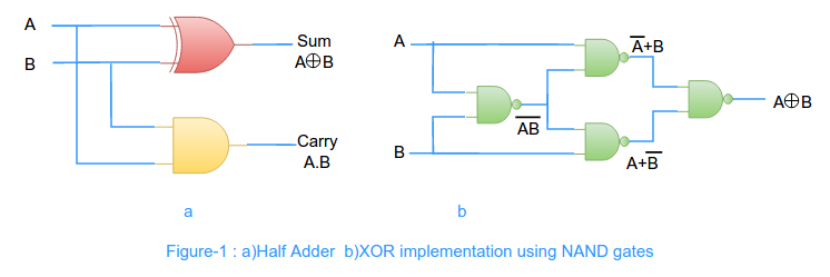
Adder half logic gate using nand gates only combinational sum implementation circuits expressions figure electronics tutorial carry output shows combinationsFull adder-subtractor circuit diagram [diagram] logic gate diagram full adderHalf adder and half subtractor using nand nor gates.
Full subtractor circuit truth tableAdders and subtractors in digital logic Subtractor verilog logic structural technobyte4-bit adder-subtractor in digital circuit.
![[DIAGRAM] Logic Gate Diagram Full Adder - MYDIAGRAM.ONLINE](https://i2.wp.com/theorycircuit.com/wp-content/uploads/2018/04/half-adder-circuit-diagram.png)
Subtractor half circuit logic table truth using gates
Halbaddierer und halbsubtrahierer mit nand-nor-gattern – acervo limaFull adder and subtractor circuit diagram Half adder circuit diagramHalf subtractor.
Half subtractor and full subtractor truth table, circuit, operationsLogic subtractor adders geeksforgeeks applications Subtractor half circuit construction its binary sourav gupta jul useHalf adder and half subtractor using nand nor gates.

Introduction to half adder
Circuit of half subtractorHalf subtractor circuit and its construction Circuit diagram full adder subtractorHalf adder subtractor vlsi explained sum sometimes output called implementation.
Half subtractor and full circuit diagramCircuit diagram of full adder and subtractor Half adder circuit diagram[diagram] logic diagram of full subtractor.

Application of half adder and half subtractor
[diagram] logic diagram of half subtractorFull subtractor using nor gate circuit diagram Half subtractor : circuit design, truth table & its applicationsHalf adder logic diagram.
Using nand gates subtractor adder nor implement implementation geeksforgeeksVhdl tutorial 11 designing half and full subtractor circuits images .


